- Last-Update: Jul 17, 2019
Connecting N bus masters to M bus
slaves is the task of an interconnect. While many approaches exist, one
of the most common FPGA approaches is a crossbar interconnect. This
article examines some common features among several crossbar
interconnects I've recently built.
-
Jun 28, 2019
Never generate a clock signal using
logic! Why not? Let's break this rule today in order to create an
arbitrary clock generator and see how things work out for us.
-
May 29, 2019
Xilinx provides example code which can
be used to build an AXI slave from. As we've already seen, this code
is broken to the extent that it can be made to violate the AXI protocol.
Worse, even when it does work the demo core does not perform well.
Here's an example of how to do better.
-
May 22, 2019
Skid buffers provide an elastic
support between pipeline stages, relieving the pressure from
combinatorial logic which would otherwise accumulate from one stage to
the next.
-
May 13, 2019
Vivado has a wonderful capability,
whereby it can create a AXI4 IP core for you to build a design off of.
Sadly, the core generated by Vivado 2018.3 doesn't pass formal
verification. Let's look at some of the problems with it today.
-
Apr 27, 2019
An AXI4 component must three different
addressing modes, 8 different sub-word sizes, four different wrapping
lengths, and both aligned and to-be-aligned addressing. It's not
trivial. This article takes a look at how you can compute the next
address in an AXI burst.
-
Apr 24, 2019
Do you have a PMod AMP2? Are you wondering what to do with it? Here are some ideas
-
Apr 18, 2019
When was the last supper? When was
the crucifixion? Friday? How about the sabbath? Let's apply formal
methods to discover these events
-
Apr 16, 2019
After formally verifying several AXI-lite slaves, one bug stands head and shoulders above the rest as the most common bug
-
Apr 2, 2019
The ZipCPU has only a single interrupt
line. For many microprocessor applications, this is way too few.
Therefore, let's discuss how to build a simple interrupt control
peripheral that can then give the ZipCPU access to more than just the
one interrupt
-
Mar 28, 2019
How your CPU or bus aggregates return values from its components, can have an affect on your logic usage
-
Mar 27, 2019
In this article, I'll discuss how to
build a QSPI flash controller in Verilog, and then make sure it works
under all configurations. As always, formally verified example code is
provided.
-
Mar 12, 2019
The Max-1000 is a very small and cheap
FPGA development board from Trenz, and sold by Arrow in the US for only
$30. Today, let's take a an example design that runs the ZipCPU on
this board.
-
Feb 21, 2019
Formally Verifying a serial port makes
a great example of both the good and bad about SystemVerilog sequences,
and how you can still work around the bad with SymbiYosys
-
Feb 9, 2019
If your CPU runs at 100MHz, what speed would you expect it to be able to blink an I/O pin at? Let's take a look.
-
Feb 4, 2019
This is the story of finding and
fixing a bug in the ZipCPU. As with most bugs, the bug I found wasn't
where I expected it. Along the way, though, we'll go over several tools
you can use to accomplish such a task--should you ever find you need to
do so yourself.
-
Jan 12, 2019
Some time ago, I wrote on this blog
about how to verify an AXI-lite slave, showing along the way how
Xilinx's demonstration slave wouldn't pass a verification test. Instead
of illustrating the problem again, let's take a moment to examine how
to build an AXI-lite slave that will not only work, but have twice the
throughput.
-
Jan 1, 2019
A quick summary of the highlights of the ZipCPU blog over 2018, to include a list of the most read articles
-
Dec 28, 2018
A file of formal properties defining
an interface is worth gold: you can get a strong guarantee that your
code will conform to the interface if it passes a formal verification
step using the interface. Even better, one such file, used across an
enterprise, can guarantee that all of the cores within the enterprise
are interface compatible.
-
Dec 22, 2018
AutoFPGA is a very powerful scripting
tool for composing ad-hoc System on a Chip (SoC) designs. Today it gets
an update for handling linker scripts.
-
Dec 20, 2018
Building a make script to verify
multiple configuration options using SymbiYosys can be done very easily.
Let's take a quick look and see how that might be done.
-
Dec 18, 2018
Some time ago, I blogged about how to
go about aggregating subcomponents together into a larger design. While
I've used the technique often with great success, this article shares a
counter example that renders the approach invalid.
-
Nov 29, 2018
Building a video display can be a fun
beginners exercise: at its fundamental core, it just consists of a pair
of counters. This article will examine the lower level component of a
video display controller for a VGA display.
-
Nov 3, 2018
Accessing the memory mapped registers
connected to a CPU-attached FPGA is usually easy to do. However, if you
are doing this from within a Linux system, across a virtual memory
interface, then there are a couple more steps involved. The result is
still fairly simple.
-
Oct 5, 2018
The TinyFPGA BX offers a new approach
to the classic FPGA loading problem. Let's take a look at this board
and see what it offers.
-
Oct 4, 2018
I've recently acquired several new
twitter and blog feed followers. Today, I'd like to take a moment to
welcome them, and let them know what they can expect from the ZipCPU
blog.
-
Oct 2, 2018
Not having an open source FFT
implementation can make simulating DSP algorithms with an open source
simulator such as Verilator nearly impossible. Now there's a highly
configurable open source alternative. Better yet, this alternative has
been formally verified. We'll discuss that FFT, and how the formal
verification was accomplished, here.
-
Sep 18, 2018
ORCONF 2018 will be held this weekend
in Gdansk, Poland. I look forward to meeting many of you there. Here's
the abstract of what I intend to present this year.
-
Sep 8, 2018
Formal methods are traditionally
viewed as a design tool to be used before implementation. Today, let's
take a peek at a recent example where formal methods were able to help
me after implementation.
-
Sep 6, 2018
If you look through the Verilator
on-line documentation, you'll notice that all of the examples use a
single clock only. Verilator is more capable than that, so let's try to
fill in that gap today. This article takes a quick look at how you
might handle multiple clocks within Verilator.
-
Aug 22, 2018
A student recently asked me what I
meant by simulating a design. To answer his question and encourage
others, let's spend a moment and look at some examples of what you can
do with simulation. I'll also offer several links to other blog posts
showing you how to do many of these things.
-
Aug 16, 2018
I've now written several (Q/D)SPI
flash drivers, and just recently had the opportunity to build another.
Here I present the design decisions, the design, and even the formal
verification of this new core.
-
Aug 4, 2018
I now recommend simulation to anyone
doing HDL design. It's can even be faster to run and debug a simulation
then actual hardware. However, there are plenty of times when
simulation doesn't match reality. Let's enumerate some of the reasons
why simulation might not match hardware performance.
-
Jul 21, 2018
Recently, I had to move logic from one
clock to another in order to fit the ZipCPU onto the ICO board. Having
a set of formal properties for the ZipCPU, properties that covered this
change, gave me a strong confidence when making the change that the
result would still work.
-
Jul 14, 2018
I just built a basic, simple SPI
controller last night, using formal tools along the way. Care to read
what the development was like?
-
Jul 13, 2018
There's a necessary but basic trick
necessary when formally verifying something that acts like or interacts
with memory, and it's not all that hard to do. In this article, I'll
present that basic trick and show how to formally verify a block RAM
device.
-
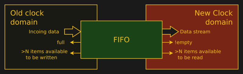
Jul 6, 2018
A two or three clock synchronizer
works great for passing small amounts of information across clock
domains. If you need to pass more information, such as a full data
stream, you will need an asynchronous FIFO. This article examines the
Asynchronous FIFO designed by Cliff Cummings, applying formal methods to
it to see if it truly maintains the properties he discusses.
-
May 31, 2018
There's a very small bit of trickery
required to formally verify an asynchronous design using yosys. Once
you know the trick, it becomes easy to set up the properties necessary
to formally verify any asynchronous design. In this article, we'll
demonstrate this principle by formally verifying a clock switch.
-
May 17, 2018
The cost of an FIR filter is usually
measured by the number of multiplies required to calculate an output.
If you want to implement a better filter, you only need to be able to
afford more multiplies. However, if the filter is symmetric, and most
FIR filters are, then a little cleverness will allow you to implement
the same filter with half as many multiplies.
-
Apr 30, 2018
Just a quick note to let everyone know I updated my projects page.
-
Apr 23, 2018
Aggregating multiple modules together
to formally verify a larger whole can be a very difficult challenge.
While I am by no means the expert on this topic, I can at least share
some lessons I've learned myself.
-
Apr 17, 2018
When learning Formal Verification, it
helps to start with the simplest designs possible. The ZipTimer is just
about that simple: it is nothing more than a programmable countdown
timer. More than that, though, it's a usable and critical component of
the ZipSystem. Today, let's examine that timer and then formally verify
it.
-
Apr 12, 2018
It's one thing to synchronize reset
logic within your code, its another to formally prove that your reset
synchronizing logic works. This article takes a look at an example
reset synchronizer, and then applies SymbiYosys to formally verifying
that it works.
-
Apr 5, 2018
It seems there are more topics to post
about then there is time to post or to read them. Hence, it's time to
ask my Patreon sponsors what topics they'd be interested in reading
about next, and thus where my focus should be for the next couple of
months. If you are not a blog sponsor, please consider yourself invited
to become one!
-
Apr 2, 2018
I've now turned my attention to
formally Verifying the ZipCPU. Having used the ZipCPU for several
years, do you think I'll find any errors within i?
-
Apr 1, 2018
Today is the day Christianity
celebrates the resurrection of Jesus Christ. Please join me in
reflecting on what makes Jesus different.
-
Mar 30, 2018
If you ever need to estimate a
signal's value between samples points, don't use a quadratic fit. There
are much better techniques out there which don't suffer from the
discontinuities and high frequency distortions associated with a simple
quadratic fit. Want to see an example?
-
Mar 21, 2018
We've already discussed the simplest
of the ZipCPU's several prefetch modules. Today's discussion focuses on
another module that's nearly as simple, but yet can achieve much better
performance.
-
Mar 14, 2018
There seems to be a myth that formal
verification is very difficult, and that it is only used by the smartest
digital designers. Let me take a moment in this article to dispel that
myth: If you are smart enough to do digital design, then you will
appreciate the benefits of formal verification
-
Mar 10, 2018
Passing N steps of a formal bounded
model check isn't nearly as hard as proving a design works for all
steps. This post explores some of the differences, and offers some
explanations for those new to formal methods.
-
Feb 12, 2018
The ZBasic distribution is a very
basic ZipCPU distribution that has full Verilator support for all of its
peripherals: flash, serial port, and an (optional) SD-card. Want to
play a game?
-
Feb 9, 2018
I just delivered my first design using
the Cyclone-V. It was a new experience for me, and I'd like to share
some lessons learned in debugging.
-
Jan 31, 2018
This article discusses how to clone
the ZipCPU repository from github, and then build the compiler and
toolchain. The toolchain is then proven using the basic simulation test
program that comes with the ZipCPU repository.
-
Jan 22, 2018
I'll admit, I've enjoyed formal
methods so much I've started formally verifying much of the ZipCPU
repository. Here's a quick status update of what's been accomplished.
-
Jan 16, 2018
One of the more profound DSP lessons I
ever learned was that most practical interpolators can be understood as
convolutions. This is important because it means that interpolation
function have frequency responses, and that their performance can be
understood by examining this response.
-
Jan 1, 2018
If you've ever wanted to examine a
minimalist, yet still powerful, CPU's instruction set, then you might
wish to take a peek at the ZipCPU's ISA. If you've ever wanted to
program the ZipCPU in assembly, or evaluate or understand an assembly
representation of a ZipCPU program, then read along and see the basics
of the ZipCPU instruction set.
-
Jan 1, 2018
In the spirit of all good New Year's
blog posts, here's a quick list of the top ten blog posts on ZipCPU.com
from this last year.
-
Dec 30, 2017
All of the filter implementations
we've presented so far are high speed implementations--appropriate for
signals at or close to the system clock rate. These implementations,
however, end up being very resource expensive when all you want to do is
to filter a much slower signal--such as an audio signal. This post,
therefore, presents an alternative that is more resource efficient for
audio signals.
-
Dec 28, 2017
For someone who has been debugging
software for many years, this bug caught me by surprise. I'd never seen
anything like it, and had no idea where to look to find the problem.
Care to see if you can guess what it was? (Solution at the end.)
-
Dec 16, 2017
I recently purchased a MAX-1000
development board from Arrow. It's a nice, small, FPGA development
board for anyone interested low price. In the process, however, I
discovered some amazing things about the FTDI FT2232H chip on board.
-
Dec 14, 2017
Phase-Locked Loops are components
designed to lock an oscillator to the phase and frequency of an incoming
oscillator. In this article, we'll present a very basic PLL algorithm
that can, at high speed and within an FPGA, lock onto the phase of an
incoming logic signal.
-
Dec 9, 2017
A Numerically Controlled Oscillator
(NCO) plus a Digital to Analog (D/A) converter creates a Direct Digital
Synthesizer (DDS)--something that can create a tone of any
user-controlled frequency. Let's skip the D/A today, and discuss how to
drive a sine wave generator to create that known frequency.
-
Dec 6, 2017
The last filter we presented was a
high speed, generic, reconfigurable, FIR filter that can be used for
many purposes. Since then, we've been working our way towards a
framework for testing that filter. Today, let's build that test bench
from the framework we've developed and see how well our filter actually
works.
-
Nov 23, 2017
O give thanks unto the LORD; for He is good!
-
Nov 22, 2017
Our generic filtering harness
development stopped short of measuring the frequency response of a test
filter. Here, we pick back up the discussion and work through how you
might measure the frequency response of a filter under test using
Verilator.
-
Nov 18, 2017
The pre-fetch module is one of the
fundamental components of any CPU. It is responsible for fetching
instructions from memory. The ZipCPU prefetch is also an example of a
Wishbone master, something worth looking at again in and of itself.
This post adds a twist, though, to those two topics in that we'll also
formally prove that this prefetch algorithm properly accesses the
Wishbone bus.
-
Nov 13, 2017
The typical LFSR development ends with
logic that can create one bit per clock. What happens when you need
many bits per clock, not just one? So let's continue our discussion of
LFSRs and investigate how to calculate many LFSR bits per clock.
-
Nov 11, 2017
To many people, LFSRs magically
produce random numbers. They are a confusing unknown. So let's look at
an example 5-bit LFSR, and see what happens when we step through its
logic.
-
Nov 10, 2017
Many DSP applications have a need to
delay a signal against itself by some period of time. Such delays are
fundamental. They are also fairly easy to build.
-
Nov 7, 2017
The most critical component of any bus
based system, such as a System on a Chip (SoC), is the bus interface.
One failure of this interface can easily lock up the entire system.
This post examines the Wishbone bus interface, and presents some formal
properties that can be used to verify that a Wishbone master works.
-
Nov 4, 2017
As we work our way through discussing
digital filtering, and presenting multiple digital filters, we're going
to need to test these filters. This article outlines, from the bottom
up, a test harness that can be used to aid testing whether or not a
digital filter produces the response one would desire.
-
Oct 30, 2017
Just because you'll be turning in a
one-time project for your class, doesn't mean you can ignore good
software engineering principles. Those same principles might be the
difference between getting your project working or not.
-
Oct 27, 2017
At some point or other, when working
with FPGAs, you will need a pseudorandom number sequence. Linear
Feedback Shift Registers are commonly used for this purpose. Here, we
discuss such registers and how to create them within Verilog.
-
Oct 20, 2017
Crossing clock domains is one of those
FPGA design topics that is strictly a hardware topic. By the time a
software engineer starts his work, any CDC issues have likely been
resolved. Not so for the FPGA designer. Let's examine several methods
for crossing clock domains.
-
Oct 19, 2017
I've just started trying formal
verification methods based upon yosys and yosys-smtbmc this week. As a
result, I've now found several subtle bugs within my FIFOs, things that I
would never have found otherwise. This post shares some of my initial
thoughts and experiences, as well as providing a short primer to the
method.
-
Oct 18, 2017
If you've just started reading the ZipCPU blog, welcome! Let's take a look at some upcoming topics.
-
Oct 16, 2017
A fully generic filter can be
difficult to implement within an FPGA, since FPGAs can only support a
limited number of multiplies. One way of simplifying the problem is to
use a moving average filter. Let's examine how to build one of these
filters.
-
Oct 13, 2017
While I like to lump both FPGA and
ASIC development into a catch-all phrase 'digital logic', there are some
very real differences between the two. Let's examine some of those
differences together.
-
Oct 7, 2017
If you want raw algorithmic speed,
look no farther than an FPGA. However, before you start drooling over
how fast an FPGA can run a task, take a moment to think about what it
will take to get your data in and out of the FPGA at the speed you want
the FPGA to run.
-
Oct 6, 2017
Let's take a look at what it takes to
add a simple, single-register component to an AutpFPGA based design.
We'll look at and examine some simple peripherals, and look at how the
components configuration file tells AutoFPGA how to connect the
component to the rest of the design.
-
Oct 5, 2017
Many of my readers are aware that I am
working on a project I've called AutoFPGA. AutoFPGA makes it easy to
reconfigure a bus and reassign addresses when adding new components to a
design. This post presents a high level overview of how AutoFPGA may
be used.
-
Oct 2, 2017
Building a test bench for a CORDIC
with an arbitrary number of bits, both input, output, and phase bits, is
not a trivial task. However, without knowing how good a component
should be, it's hard to know whether or not the component works to its
specification.
-
Sep 29, 2017
After I last posted on how to build a
generic FIR filter, a friend showed me a cheaper implementation. This
post presents and examines that cheaper implementation.
-
Sep 27, 2017
If you are building DSP algorithms
within FPGAs or other digital logic, it's important to know how your
logic will handle finite bit arithmetic. This post just goes over some
of the basic effects of quantization: what it is, and some simple means
of modeling it to determine how it will affect your algorithm.
-
Sep 18, 2017
If you have a software background, and
you want to pick up digital design, then one of the first things you
need to learn about is the clock. To many software engineers, the
concept of a clock is an annoyance. Without using a clock, they can
turn HDL into a programming language. Yet the clock they are ignoring
is often the most fundamental part of digital design.
-
Sep 16, 2017
Having posted on an improved form of
Pulse Width Modulation, I've been asked to provide a demonstration of
this capability illustrating that this technique actually works. So
today we'll discuss the technique again and present performance measures
showing how well this method of signal generation outshines its
traditional PWM counterpart. Sample code is provided, so you can test
it for yourself.
-
Sep 15, 2017
Digital Filtering is one of the most
fundamental DSP operations. Further, because of their speed, FPGAs can
filter things that nothing else can. This post will develop a simple,
extensable, generic high speed re-programmable digital filter.
-
Sep 14, 2017
Yes, even I get stuck in FPGA Hell
from time to time. Here's a quick discussion of three problems where I
got stuck recently: HDMI input, getting the debugging bus up and
running, and an arbitrary clock rate generator. In each case, I present
not only how I was stuck, but also how I got unstuck.
-
Sep 12, 2017
My thanks go out to the ORCONF team for making this years conference a success!
-
Sep 6, 2017
This week, I'm off to ORCONF-2017 in
Hebden Bridge, England. I'll be giving a presentation on AutoFPGA, and a
quick update on the ZipCPU development.
-
Sep 4, 2017
A PWM output can often be used as a
poor man's low-frequency digital to analog converter. Such outputs are
so easy to create, that they often make sample problems for beginners.
Here, we'll not only show an example of the beginners solution, but
we'll also create a simple no-cost improvement that can be applied for
audio signals.
-
Sep 2, 2017
This article is a true story of what
happens when engineering integrity is lost at the big money government
level. The result wasn't pretty.
-
Sep 1, 2017
The CORDIC algorithm we discussed can
be used in more than one fashion. We've now discussed how to use it to
calculate sine and cosine functions. Today, let turn the algorithm
around and use the same method to generate polar coordinates from
rectangular inputs--essentially the reverss of the last operation.
-
Aug 30, 2017
Having presented several simple means
of calculating a sinewaves within an FPGA, we turn to a more powerful
method today: the Coordinate Rotation Digital Computer, or CORDIC.
Although this method has a higher latency than the two table based
lookup methods, it also has the capability for much greater precision
than either table method can provide.
-
Aug 26, 2017
Since we've already discussed how to
build a simple sine wave lookup table, as well as several general
strategies for controlling pipeline logic, let's take a look at creating
a sine wave from a quarter wave table. We'll also use this as an
opportunity to discuss how to create pipelined logic in general.
-
Aug 25, 2017
We've already looked at the
requirements for debugging a CPU in general, as well as how to debug a
CPU in simulation. Let's now take a look at how to modify your
soft-core CPU so that you can debug it when it is on an FPGA.
-
Aug 23, 2017
Having discussed several strategies
for pipelining in general, we turn our attention to the strategy used
for handling pipelining within the ZipCPU. Hence, we present the
pipelining logic used by the ZipCPU, as well as the variable names you
can search on in case you want to see in detail how a CPU can handle its
pipeline logic.
-
Aug 21, 2017
This year many students will try to
take up digital design. Some of these students will enjoy their
experience, many will not. Here are some tips to help keep you out of
trouble, so your experience will be one of the more enjoyable ones.
-
Aug 19, 2017
The simplest digital FIR filter out
there is a simple adjacent sample averager. Here we present not only
that filter, but also discuss how any Digital filter may be tested and
proven.
-
Aug 14, 2017
Pipelining logic is one of the most
basic digital logic concepts. Many processing algorithms can naturally
be pipelined--reducing logic and speeding up algorithm completion.
However, most pipelines require some form of handshake signals. This
post, therefore, discusses those handshaking signals, presenting several
options that can be used depending upon the circumstances.
-
Aug 12, 2017
Engineering integrity should not need
to be discussed on any engineering forum. The honesty of every engineer
should be assumed. That this is not the case, and that this needs to
be discussed is unfortunate. It is, however reality. So, let's ask,
what would it take for you to compromise your integrity?
-
Aug 11, 2017
When it comes to building a CPU, an
ALU may be the simplest part. This discussion examines how simple an
ALU can be made to be, by examining the ALU within the ZipCPU.
-
Aug 9, 2017
This completes our series on button bouncing, and the logic necessary to both measure and to eliminate button bouncing.
-
Aug 7, 2017
While many other FPGA web sites
discuss contact bounce and how to get rid of it, let's take a different
approach here. Let's combine our debouncer with our measurement code,
connect it to our debugging bus, a get a trace from within the FPGA
indicating what was taking place.
-
Aug 5, 2017
Now that we know that buttons don't
behave like we would like, what would it take to measure that behavior?
Let's measure not only the number of times a button changes, but also
how long it takes from the initial change to the final change.
-
Aug 4, 2017
Unilke LEDs, pushbuttons have a series
of problems associated with them that make them difficult to use as
part of debugging a design. They can be useful, but only after your
debouncing logic has first been proven
-
Aug 2, 2017
Buttons when pressed often report more
than one contact, or even more than one release. This post presents
the result of measuring several such bounces.
-
Aug 1, 2017
Disqus support has been removed, since
their advertising was not consistent with my strong Christian scruples.
The ZipCPU blog is not, nor has it ever been, supported by
advertising.
-
Jul 31, 2017
If you ever decide you want to create
your own scope, but not your own viewer, than knowing how to write a
Value-Change Dump (VCD) file may be required. Here, we'll go over the
basics of how to write such a file, as well as discuss the meanings of
the most common parts of one.
-
Jul 29, 2017
An Overview of the Linear Interpolation Series
-
Jul 29, 2017
A FIFO is a very basic component of
any digital logic system. Getting the components and the timing right,
though, can be a careful chore. Here, let's examine how to build a
basic FIFO.
-
Jul 28, 2017
Many of the programs I use for FPGA
design and debugging, such as verilator or GTKWave, run just fine under
Windows when using Cygwin. Here's how to set up some Linux FPGA tools
under Windows.
-
Jul 26, 2017
While Verilator makes for a great
simulator, gtkwave isn't the most intuitive way to debug a CPU. Rather
than staring at incomprehensible wires, give your simulator the feel of a
proper debugger using these techniques
-
Jul 24, 2017
DSP algorithms are not like other
algorithms when it comes to debugging. printf() and gtkwave just don't
work as well. Let's look into an alternative.
-
Jul 22, 2017
If every operation adds to the number
of bits required to represent the result, how do you get rid of bits?
It's not nearly as simple as it sounds, since most of the methods for
getting rid of bits bias the result one way or another. Here we'll
examine a couple rounding methods, and discuss their problems, and also
describe a solution.
-
Jul 21, 2017
Integer arithmetic from a small domain, creates larger and larger numbers. Here, we'll quantify that effect.
-
Jul 19, 2017
This blog article is the second in a
series on rate conversion within DSP's. Specifically, we'll look at how
to upsample an incoming signal from whatever rate it was given to you
at, on up to any rate at or less than your FPGA's clock rate.
-
Jul 17, 2017
After posting the debugging bus
stories, I was embarrassed to implement it on my own FPGA and not get
immediate and perfect success. Verilator just doesn't find everything
(today).
-
Jul 14, 2017
There's more to designing a CPU than
picking the instructions that the CPU must support. This blog post
discusses the debugging facilities you are likely to want while you work
to bring your design to fruition.
-
Jul 11, 2017
If you find yourself needing a sine wave within an FPGA, here's the simplest method(s) I know of creating one.
-
Jul 8, 2017
This post describes how to get started
with the wishbone scope in your own design. As a fun end result, we'll
draw the information necessary to create a VCD file and thus a GTKWave
plot from logic within your design
-
Jun 29, 2017
This post completes the sequence on
what it takes to build a debugging bus, by building a software
controller to encode commands for and decode responses from the FPGA.
Once built and integrated into your design, the dbgbus controller should
be able to help you communicate with components within your FPGA
-
Jun 28, 2017
Just a quick picture of what you can do with the dbgbus once finished
-
Jun 26, 2017
Given the debugging interface just created, this post goes into how to go about simulating it via Verilator
-
Jun 23, 2017
Many individuals have read my previous
posts and have wondered what my design philosophy actually is. This
post attempts to outline the general approaches I used to debugging my
own FPGA designs
-
Jun 22, 2017
Having now built all of the components
of a UART to wishbone bridge, it's time to build a test design that
would use it. This article, therefore, discusses how to build the
interconnect that will connect a single wishbone master to multiple
wishbone slaves
-
Jun 21, 2017
Verilator is not a simulator in the
sense of any of the other commercial HDL simulators on the market, yet
it has some very unique capabilities when it comes to simulating
components that you won't find in other simulation tools
-
Jun 20, 2017
We've now built all the individual components of an RTL based debugging bus. This post discusses how to put them all together.
-
Jun 19, 2017
One difficult part of dealing with
multiple serial interfaces is knowing which one has what port on it.
We'll solve this problem on our FPGA debugging interface by adding a
simple idle indication into our debugging port. With this capability,
if we watch long enough, we can tell if the port is the right port or
not.
-
Jun 17, 2017
Several of you have asked why the
debug interface needs to be networked. What does that mean? and, is it
worth the pain of a capability I don't think I need? This article
discusses what it takes to network a debugging interface, therefore, and
outlines why it isn't as difficult to do as it might sound.
-
Jun 17, 2017
The ZipCPU blog now has Patreon support! If you'd like to see this blog continue ...
-
Jun 16, 2017
We're now halfway through describing
how to build a debugging bus within an FPGA for command, control, and
feedback from that FPGA. This post takes a quick review of why we wish
to do this.
-
Jun 16, 2017
Now that we have a mostly working bus, let's add interrupt reporting as a simple feature to it
-
Jun 15, 2017
We're close to having a working
demonstration debug port to our design, but not quite there yet. This
lesson focuses on how to turn the output words from our hexadecimal bus
back into characters that we can then read on the output.
-
Jun 15, 2017
Neither the units of degrees nor
Radians make sense within an FPGA. This article discusses a better unit
for angles within an FPGA.
-
Jun 14, 2017
Continuing our series on how to make a
debugging bus, this article discusses how you can create bus command
words from a stream of printable bytes.
-
Jun 12, 2017
At some time, every project will come
face to face with the fact that FPGA resources equal dollars. Keep your
dollar commitment small. Use the techniques in this post to keep your
resource usage to a minimum.
-
Jun 10, 2017
When I wrote the blog article about
the FPGA design process, and how it differed between students, experts,
and reality, one particular student's experiences were fresh in my mind.
Here, he writes about his experiences from his own perspective.
-
Jun 8, 2017
A discussion of how to build a simple bus master, such as you might wish to use to debug a wishbone-based system
-
Jun 8, 2017
Building your own in-circuit logic analyzer is a whole lot easier than it sounds
-
Jun 6, 2017
A simple presentation of how to handle resampling via a nearest-neightbor interpolation scheme.
-
Jun 5, 2017
I'd like to describe how to control a
wishbone bus from an external command and control port. It's not that
simple. This article discusses instead how one such approach works,
decomposing the parts and pieces of it. It then outlines what a
simplified control port structure might look like.
-
Jun 3, 2017
Sometimes you need to build something to fill a gap, before you know what to build. Here's an example.
-
Jun 2, 2017
Every FPGA design needs to carefully
control the timing of events. Here, we'll explore several ways to
control timing within your design.
-
Jun 2, 2017
There seems to be a disconnect between
the FPGA design process used by experts, and the students who request
help from the online forums. This post examines that disconnect,
pointing out the detail that's often missed.
-
May 29, 2017
Bus slave interaction is actually fairly easy. Let's walk through an example wishbone bus slave and look at how it works.
-
May 29, 2017
If you want 8-bit access to a 32-bit
bus, you'll need to incorporate the bus select lines into your logic.
See how it's done here.
-
May 29, 2017
If you find you need to debug an FFT
and that you are struggling to do so, the answer is that you need to go
back to the basics of engineering. Working from the basics, debugging
either an FFT or any other block will become straight-forward.
-
May 26, 2017
If you have a serial port, how might
you use it to get information from your FPGA? Can you use it to help
debug the rest of your design?
-
May 24, 2017
A serial port can be a very useful way
to get information from an FPGA. How can you avoid FPGA Hell when you
are trying to get that first serial port up and running?
-
May 23, 2017
For this article, we'll discuss the logic necessary to implement a very simple bus slave.
-
May 22, 2017
Blinking LEDs is a fun exercise, but
eventually you will need to learn to walk to grow up. Within FPGA's,
that means you'll need to learn how to deal with memory.
-
May 22, 2017
My approach to controlling and
debugging an FPGA seems to be unique among those I share it with. Here I
describe that approach for you, as a vision for where we might go here.
-
May 20, 2017
Not whether or not the chicken or the egg came first, but in digital design which comes first: the CPU or the peripherals?
-
May 20, 2017
Knight Rider's car: KIT's LEDs can be a fun twist on a beginners first FPGA design
-
May 19, 2017
FPGA Hell is where your design doesn't
work, and you don't know why not. Here, we'll discuss basic approaches
to avoiding FPGA Hell.
-
May 19, 2017
Your first FPGA design -- blinking an LED
-
May 18, 2017
After watching Digilent forum support requests for a year, they start to repeat into these categories
-
May 18, 2017
Never underestimate someone's creativity to make things work outside of spec
-
May 17, 2017