CryptoURANUS Economics

Anti-AdBlocker

Sunday, February 9, 2020

Ref: VHDL Tutorial: Learn by Example

We are the present moment, we are love.


 VHDL Tutorial: Learn by Example
-- by Weijun Zhang, July 2001

NEW BOOKS, See the new books on: FPGA, Digital Design: Online Interactive zyBook, HDL, VHDL, Verilog, System-Virlog

If we hear, we forget; if we see, we remember; if we do, we understand.
                                                                      --  Proverb
ESD book | VHDL Projects | VHDLReference | Auburn.edu_SynopsysTutorial | ActiveHDLTutorial | VHDL_Online_Tutorial
  Table of Contents
Foreword
Basic Logic Gates
Combinational Logic Design
Typical Combinatinal Logic Components
Latch and Flip-Flops
Sequential Logic Design
Typical Sequential Logic Components
Custom Single-Purpose Processor Design
General-Purpose Processor Design
Appendix: Modeling an industry core


Foreword (by Frank Vahid)
<> HDL (Hardware Description Language) based design has established itself as the modern approach to design of digital systems, with VHDL (VHSIC Hardware Description Language) and Verilog HDL being the two dominant HDLs. Numerous universities thus introduce their students to VHDL (or Verilog). The problem is that VHDL is complex due to its generality. Introducing students to the language first, and then showing them how to design digital systems with the language, tends to confuse students. The language issues tend to distract them from the understanding of digital components. And the synthesis subset issues of the language add to the confusion.
We developed the following tutorial based on the philosophy that the beginning student need not understand the details of VHDL -- instead, they should be able to modify examples to build the desired basic circuits. Thus, they learn the importance of HDL-based digital design, without having to learn the complexities of HDLs. Those complexities can be reserved for a second, more advanced course. The examples are mostly from the textbook Embedded System Design by Frank Vahid and Tony Givargis. They start from basic gates and work their way up to a simple microprocessor. Most of the examples have been simulated by Aldec ActiveHDL Simulator and Synopsys Design Analyzer, as well as synthesized with Synopsys Design Compiler . Several sequential design examples have been successfully tested on Xilinx Foundation Software and FPGA/CPLD board.


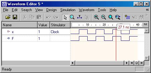
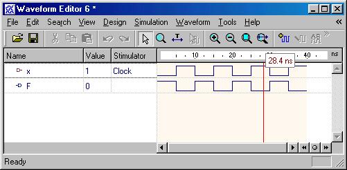
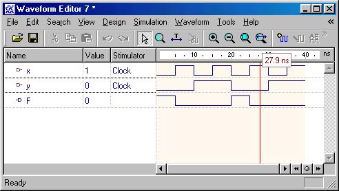
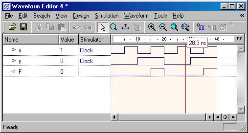
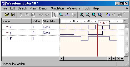
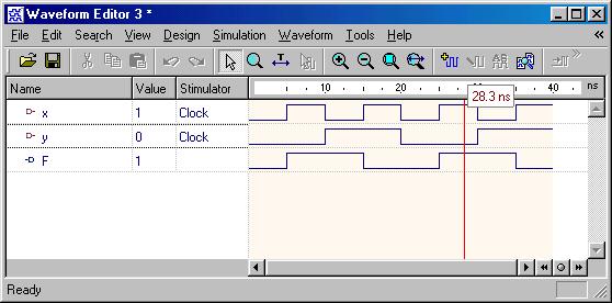
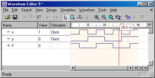
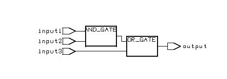
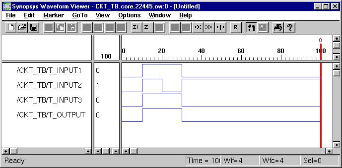
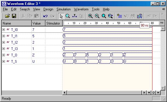
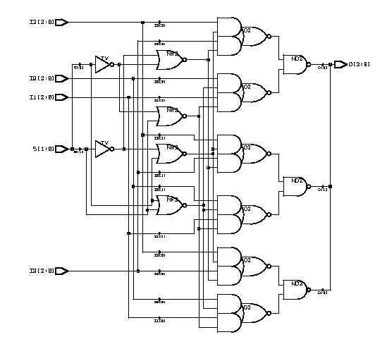
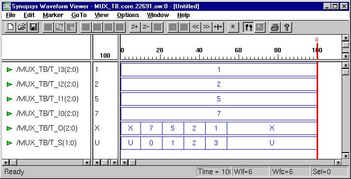
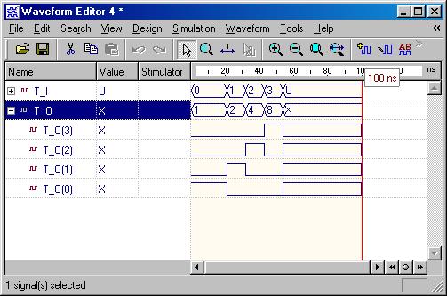
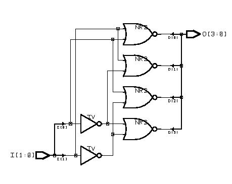
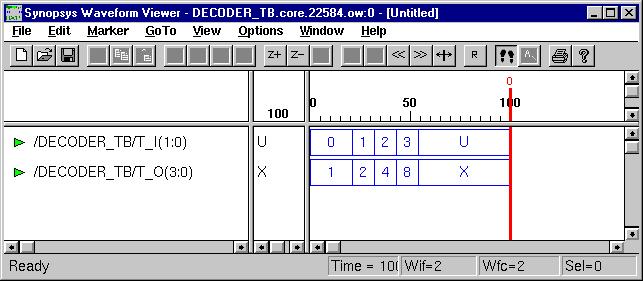
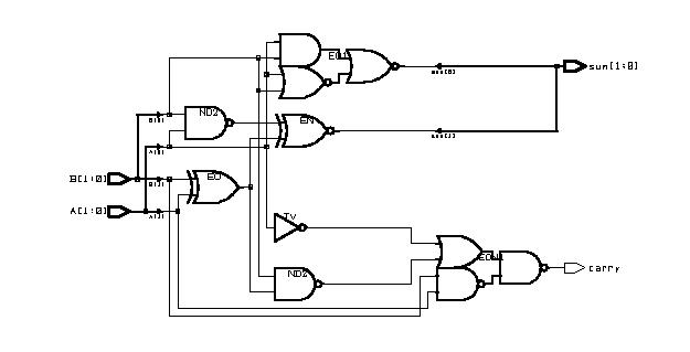
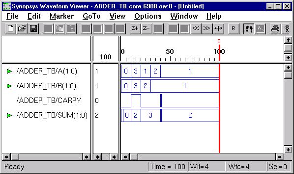
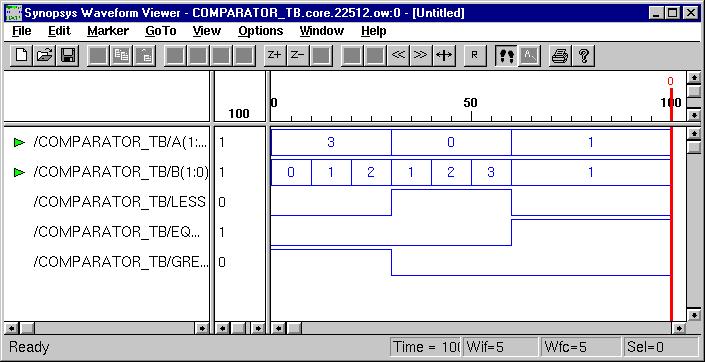
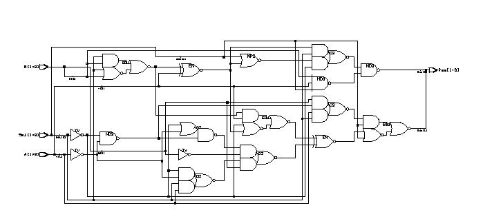
Basic Logic Gates
(ESD Chapter 2: Figure 2.3)
Every VHDL design description consists of at least one entity / architecture pair, or one entity with multiple architectures. The entity section of the HDL design is used to declare the I/O ports of the circuit, while the description code resides within architecture portion. Standardized design libraries are typically used and are included prior to the entity declaration. This is accomplished by including the code "library ieee;" and "use ieee.std_logic_1164.all;".
 Driver 
 Behavior Code
Behavior Simulation
 Inverter 
 Behavior Code
Behavior Simulation
 OR gate
 Behavior Code
Behavior Simulation
 NOR gate 
 Behavior Code
Behavior Simulation
AND gate
Behavior Code
Behavior Simulation
NAND gate
Behavior Code
Behavior Simulation
 XOR gate
 Behavior Code
Behavior Simulation
 XNOR gate
 Behavior Code
Behavior Simulation


Combinational Logic Design
(ESD Chapter 2: Figure 2.4)
We use port map statement to achieve the structural model (components instantiations). The following example shows how to write the program to incorporate multiple components in the design of a more complex circuit. In order to simulate the design, a simple test bench code must be written to apply a sequence of inputs (Stimulators) to the circuit being tested (UUT). The output of the test bench and UUT interaction can be observed in the simulation waveform window.
Combinational Logic
Behavior Code
Test Bench
 Behavior Simulation
Synthesis Schematic
Gate-level Simulation
Tri-State Driver
Behavior Code
Test Bench
Behavior Simulation
Synthesis Schematic
Gate-level Simulation

Discussion I: Signal vs. Variable Siganls are used to connect the design components and must carry the information between current statements of the design. On the other hand, variables are used within process to compute certain values. The following example shows their difference: 
 
Signal/Variable Example
Behavior Code
Behavior Simulation


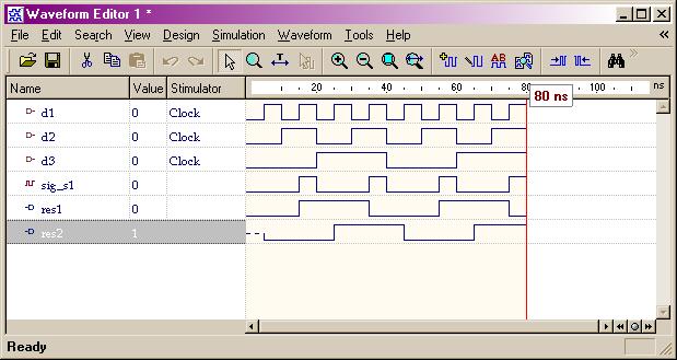
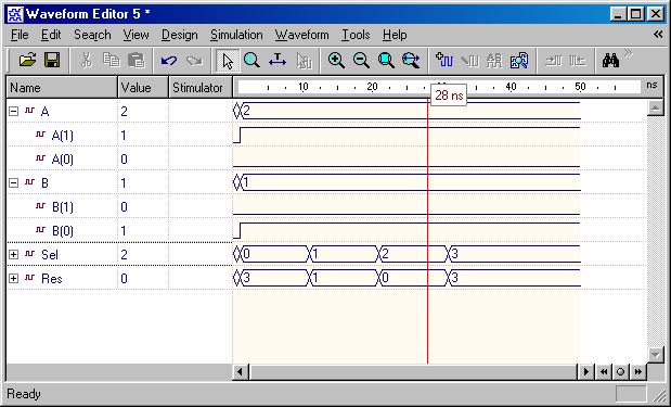
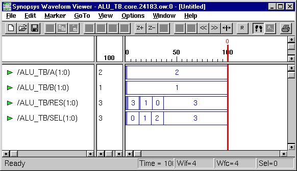
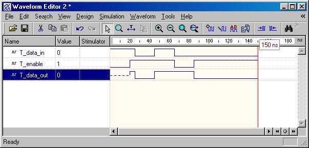
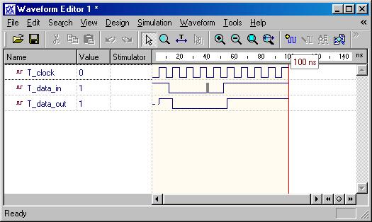
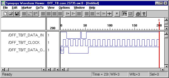
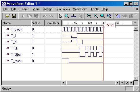
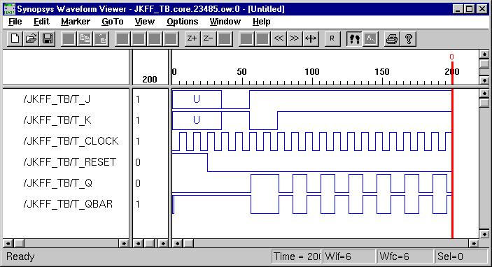
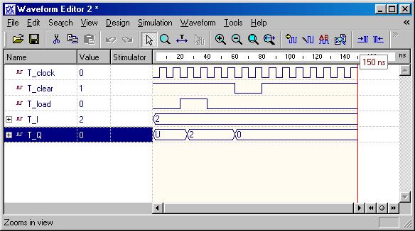
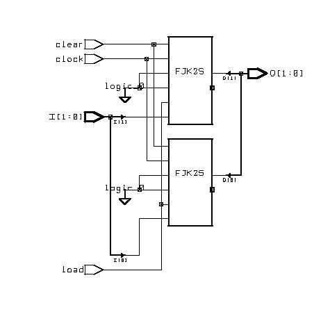
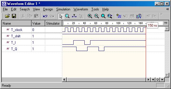
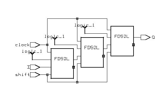
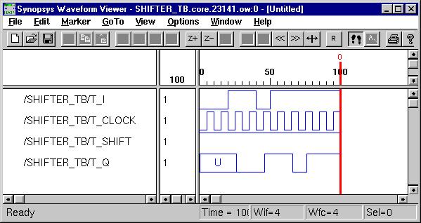
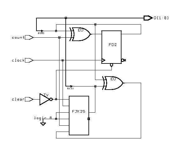
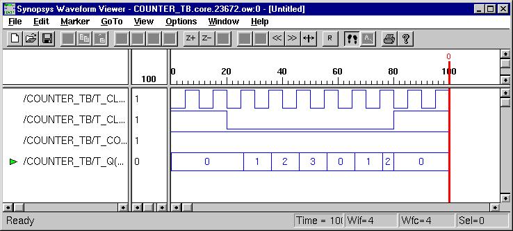
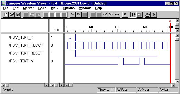
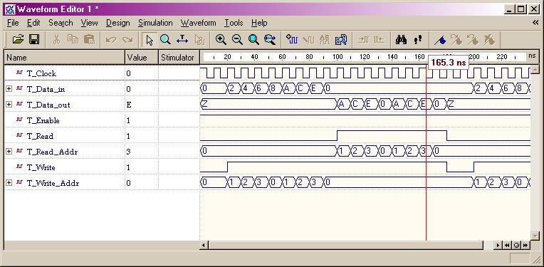
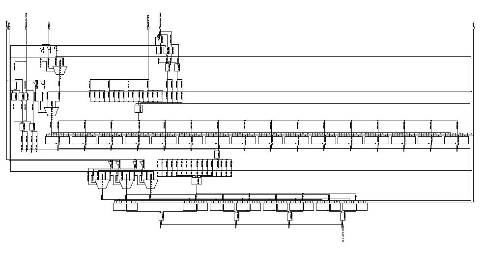
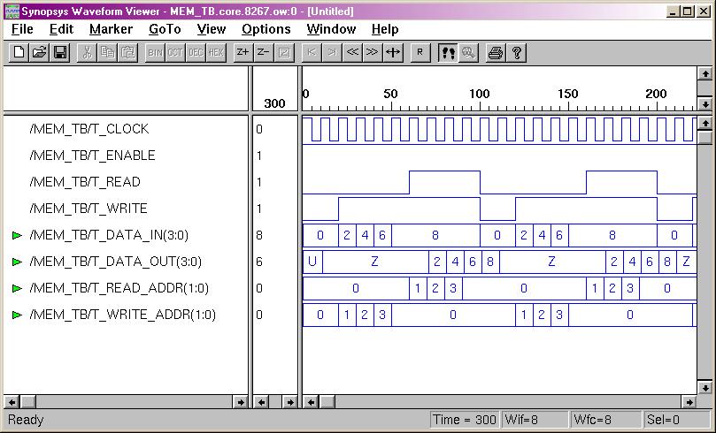
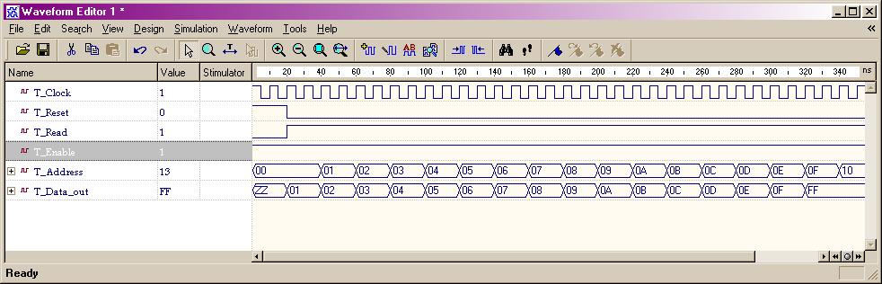
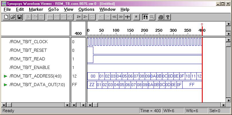
Typical Combinational Components
(ESD Chapter 2: Figure 2.5)
The following behavior style codes demonstrate the concurrent and sequential capabilities of VHDL. The concurrent statements are written within the body of an architecture. They include concurrent signal assignment, concurrent process and component instantiations (port map statement). Sequential statements are written within a process statement, function or procedure. Sequential statement include case statement, if-then-else statement and loop statement.
 Multiplexor
Behavior Code
Test Bench
Behavior Simulation
Synthesis Schematic
Gate-level Simulation
 Decoder
Behavior Code
Test Bench
Behavior Simulation
Synthesis Schematic
Gate-level Simulation
 Adder
Behavior Code
Test Bench
Behavior Simulation
Synthesis Schematic
Gate-level Simulation
 Comparator
Behavior Code
Test Bench
Behavior Simulation
Synthesis Schematic
Gate-level Simulation
 ALU
Behavior Code
Test Bench
Behavior Simulation
Synthesis Schematic
Gate-level Simulation
Multiplier
Behavior Code
Test Bench
Behavior Simulation
Synthesis Schematic
Gate-level Simulation


Latch & Flip-Flops
(ESD Chapter 2.3)
Besides from the circuit input and output signals, there are normally two other important signals, reset and clock, in the sequential circuit. The reset signal is either active-high or active-low status and the circuit status transition can occur at either clock rising-edge or falling-edge. Flip-Flop is a basic component of the sequential circuits.
 Simple Latch
Behavior Code
 Test Bench
Behvaior Simulation
Gate-level Implementation
Gate-level Simulation
D Flip-Flop
Behavior Code
Test Bench
Behavior Simulation
Gate-level Implementation
Gate-level Simulation
JK Flip-Flop
Behavior Code
Test Bench
Behavior Simulation
Gate-level Implementation
Gate-level Simulation


Typical Sequential Components
(ESD Chapter 2: Figure 2.6)
Typical sequential components consist of registers, shifters and counters. The concept of generics is often used to parameterize these components. Parameterized components make it possible to construct standardized libraries of shared models. In the behavioral description, the output transitions are generally set at the clock rising-edge. This is accomplished with the combination of the VHDL conditional statements (clock'event and clock='1'). During the testbench running, the expected output of the circuit is compared with the results of simulation to verify the circuit design.
 Register
Behavior Code
 Test Bench
Behavior Simulation
Gate-level Implementation
Synthesis Schematic
Structural Simulation
Shift Register
Behavior Code
 Test Bench
Behavior Simulation
Gate-level Implementation
Synthesis Schematic
Structural Simulation
 Counter
Behavior Code
 Test Bench
Behavior Simulation
Gate-level Implementation
Synthesis Schematic
Structural Simulation


Sequential Logic Design
(ESD Chapter 2: Figure 2.7)
The most important description model presented here may be the Finite State Machine (FSM). A general model of a FSM consists of both the combinational Logic and sequential components such as state registers, which record the states of circuit and are updated synchronously on the rising edge of the clock signal. The output function computes the various outputs according to different states. Another type of sequential model is the memory module, which usually takes a long time to be synthesized due to the number of design cells.
FSM Model
Behavior Code
Test Bench
Behavior Simulation
Gate-level Implementation
Synthesis Schematic
Gate-level Simulation
    • Memories (ESD Chapter 5)
RAM Module
Behavior Code
Test Bench
Behavior Simulation
Gate-level Implementation
Synthesis Schematic
Gate-level Simulation
ROM Module
Behavior Code
Test Bench
Behavior Simulation
Gate-level Implementation
Synthesis Schematic
Gate-level Simulation

Discussion II: Behavior vs. RTL Synthesis (Y Chart) RTL stands for Register-Transfer Level. It is an essential part of top-down digital design process. Logic synthesis offers an automated route from an RTL design to a Gate-Level design. In RTL design a circuit is described as a set of registers and a set of transfer functions describing the flow of data between the registers, (ie. FSM + Datapath). As an important part of a complex design, this division is the main objective of the hardware designer using synthesis. The Synopsys Synthesis Example illustrates that the RTL synthesis is more efficient than the behavior synthesis, although the simulation of previous one requires a few clock cycles. 
 
GCD Caculator 
Behavior Code
RTL Code (FSM+D)
Comparison
Following section illustrates the RTL (FSM+Datapath) method further using several design examples.


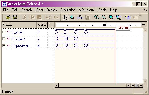
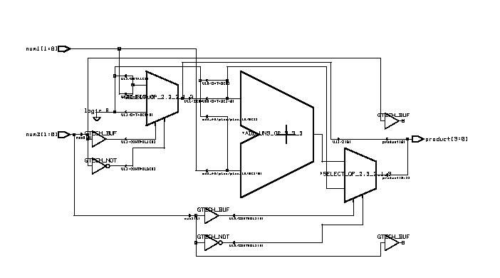
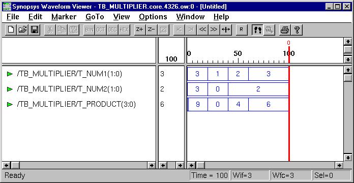
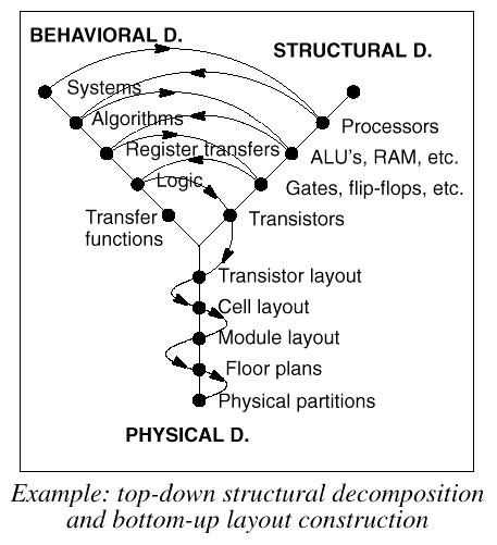
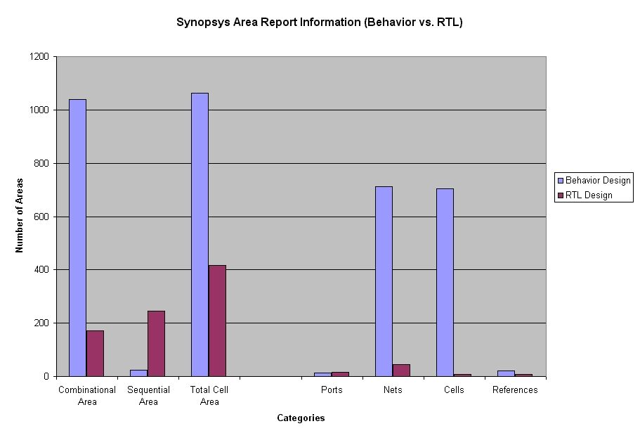
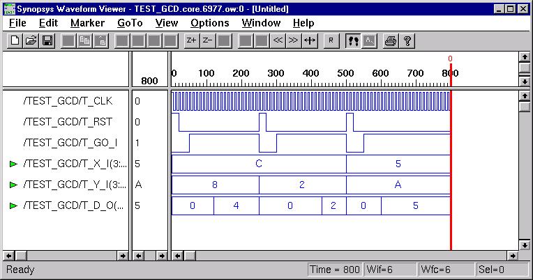
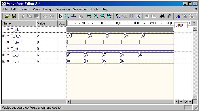
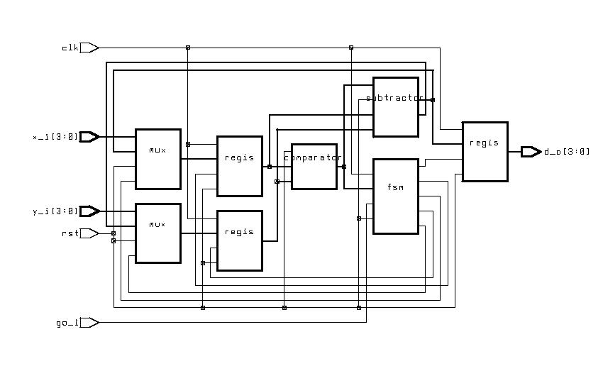
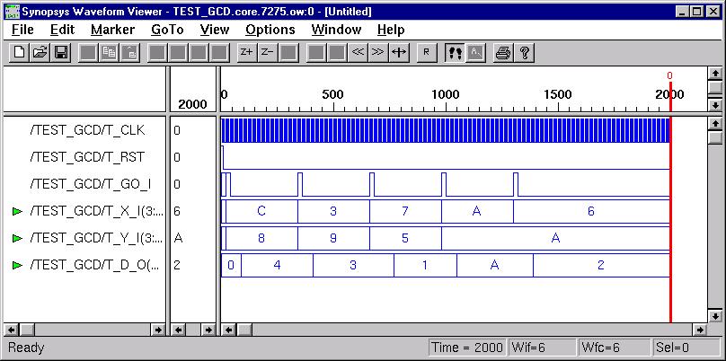
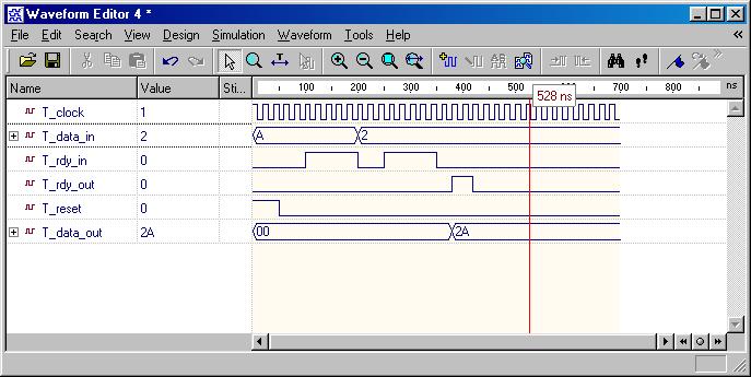
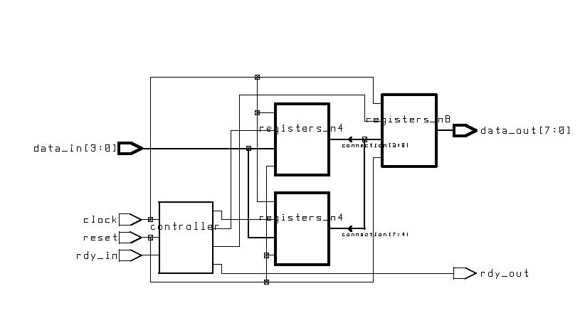
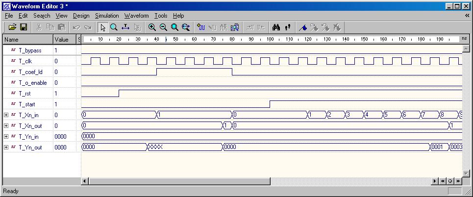
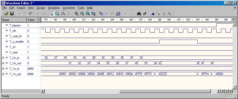
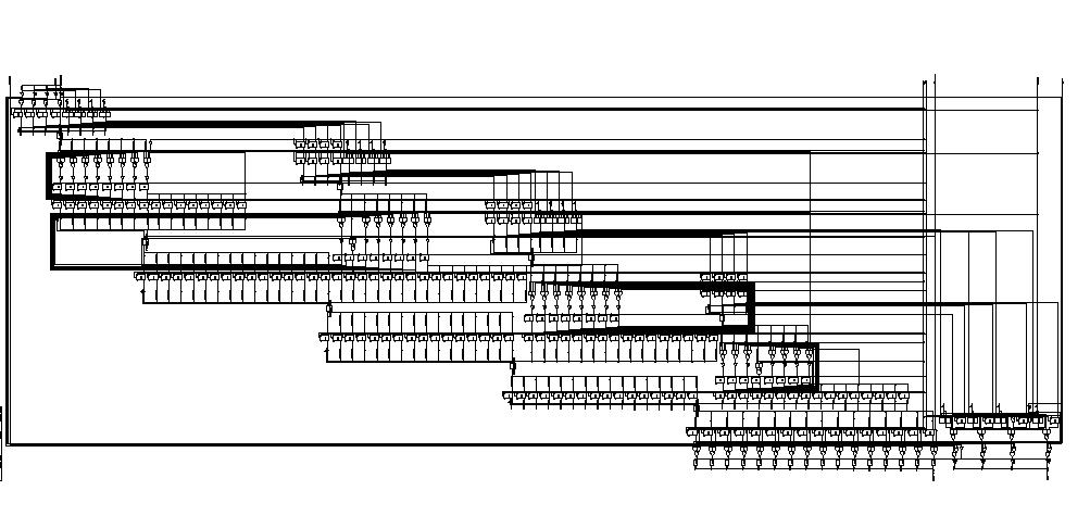
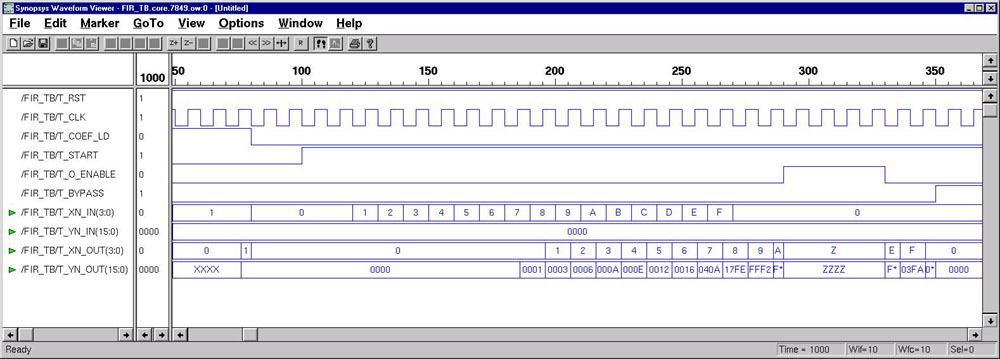
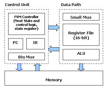
Custom Single-Purpose Processor Design
(ESD Chapter 2, Chapter 4)
The first three examples illustrate the difference between RTL FSMD model (Finite State Machine with Datapath buildin) and RTL FSM + DataPath model. From view of RT level design, each digital design consists of a Control Unit (FSM) and a Datapath. The datapath consists of storage units such as registers and memories, and combinational units such as ALUs, adders, multipliers, shifters, and comparators. The datapath takes the operands from storage units, performs the computation in the combinatorial units, and returns the results to the storage units during each state. This process typically takes one or two clock cycles.  Data-flow (looks more like an Algorithm) modeling is presented in the fourth example. The FIR digital filter algorithm is simulated and synthesized using VHDL. A comparison of the coding styles between the RTL modeling and Algorithm level modeling highlights the different techniques.
    • GCD Calculator (ESD Chapter2: Figure 2.9-2.11)
FSMD Modeling
RTL Code
Test Bench
RTL Code Simulation
Gate-level Implementation
Synthesis Schematic
Gate-level Simulation
 FSM + Datapath Modeling
RTL Code
Test Bench
RTL Code Simulation
Gate-level Implementation
Synthesis Schematic
Gate-level Simulation
    • Simple Bridge (ESD Chapter 2: Figure 2.13-2.14)
FSMD Modeling
RTL Code
Test Bench
RTL Code Simulation
Gate-level Implementation
Synthesis Schematic
Gate-level Simulation
FSM + Datapath Modeling
RTL Code
Test Bench
RTL Code Simulation
Gate-level Implementation
Synthesis Schematic
Gate-level Simulation
    • ISA Bus Interface (ESD Chapter 4, Chapter 6)
FSM + Datapath Modeling
RTL Code
Test Bench
RTL Code Simulation
Gate-level Implementation
Synthesis Schematic
Gate-level Simulation
    • FIR Digital Filter (DSP Example)
Data-Flow Modeling
Behavior Code
Test Bench
Behavior Simulation(1,2)
Gate-level Implementation
Synthesis Schematic
Gate-level Simulation
 

Discussion III: Synopsys Power Analysis
Synopsys tools can be used to perform Power Analysis for all the VHDL designs. Generally, the better design has smaller power consumption. On the other hand, improve the power always means sacrificing other design metrics such as performance, area size or NRE cost. Therefore, a designer need to balance these metrics to find the best implementation for the given application and constraints. Please check out the power analysis results of Adder, Counter, ISA controller, Bridge controller and FIR Filter. As we expected, FIR digital filter has the biggest power consumption because it has a more complex circuit doing DSP computation. Synopsys power analysis tutorial can be found here.
Discussion IV: Synthesis withTiming Constraints When we design and simulate the high-level (either behavior or RTL) code, we only care about design functionality. However, in VHDL synthesis, the timing and the functionality of a design must always be considered together. Therefore, once the design has been synthesized, the second goal of simulation is to quickly verify that the gate-level implementation meets timing requirements. We use this idea (coding -> simulation -> synthesis -> simulation) to test all of the examples in this tutorial. 
Another common way is to apply the timing constrains on the design during synthesis. then the timing report is checked to see if the slack, which is the required delay minus the actual delay, is MET or VIOLATED. If VIOLATED, we should go back to the VHDL code and re-write it to improve timing. The whole design will be compiled and tested again. 
 
Counter
Behavior Code
Sythesis Script File
Timing Report
Discussion V: Relationship between Area and Timing
During Synopsys synthesis, ordinary combinational logic will go through several of what are known as mapping optimizations. In a normal optimization, the synthesis tool will optimize in relation to the set constrains. It is usual to talk about moving along a "banana curve" on the area and time axes. This means that the tougher the timing constrains, the larger the design will be, and vice versa. The results from two different synthesis constrains applied on the same design are shown below.
 
FIR filter
Sample Synthesis Script
Comparison Table
Banana Curve


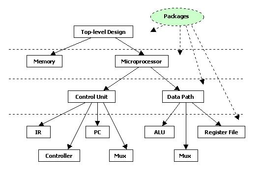
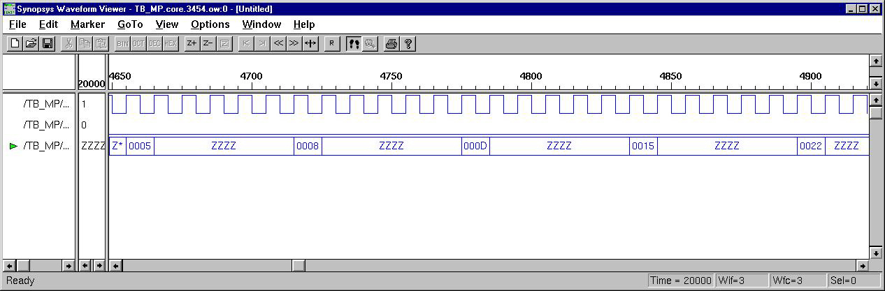
General-Purpose Processor Design
(ESD Book Chapter 3, Figure 3.15)
As indicated in the previous part, an Application Specific Integrated Circuit (ASIC) is specified with behavior descriptions which are presented in the form of particular algorithm or flowchart. A general purpose processor, on the other hand, is specified completely by its instruction set (IS). A sequence of instructions is required for the computation of a mathematical expression or any other similar computational task. To illustrate the whole procedure, a simple Pseudo-Microprocessor model is used which contains seven instructions (ESD book figure 3.7). The RT level design method from previous examples is used again to construct this microprocessor. The CPU will fetch, decode, and execute each instruction in order to get the final result.  For test purposes, a short program (sequential instructions) is loaded into the memory. After execution, this program will obtain 10  Fabonacci Numbers, and store the results into specific memory address. The design was implemented using Active-HDL and Synopsys Design Compiler. (Please note that PC.vhd need a little modify to get correct synthesis result. Just a practice for the reader.)
 
Top Level Structural Code
microprocessor.vhd
Design Hierarchy
cpuhierarchy.jpg
Test Bench of CPU Design
TB_mp.vhd
Control Unit
ctrl_unit.vhd
Block Diagram
cpublock.jpg
Data Path
datapath.vhd
controller.vhd  PC.vhd
IR.vhd   bigmux.vhd
Memory
memory.vhd
smallmux.vhd reg_file.vhd
alu.vhd obuf.vhd
Synopsys Sythesis Script Files
cpusyn.scr
syn_ctrl_unit.inc, syn_PC.inc, syn_IR.inc, syn_datapath.inc, syn_reg_file.inc
syn_alu.inc, syn_memory.inc
syn_controller.inc, syn_obuf.inc, syn_bigmux.inc, syn_smallmux.inc
Behavor Simulation 
Script File
cpusim.scr
Simulation Waveform
cpusim1.jpg cpusim2.jpg
Gate-Level Simulation 
Script File
cpugatesim.scr

Discussion V: VHDL vs. Verilog There are now two industry standard hardware description languages, VHDL and Verilog. It is important that a designer knows both of them although we are using only VHDL in class. Verilog is easier to understand and use. For several years it has been the language of choice for industrial applications that required both simulation and synthesis. It lacks, however, constructs needed for system level specifications. VHDL is more complex, thus difficult to learn and use. However it offers a lot more flexibility of the coding styles and is suitable for handling very complex designs. Here is a great article to explain their difference and tradeoffs. 


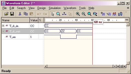
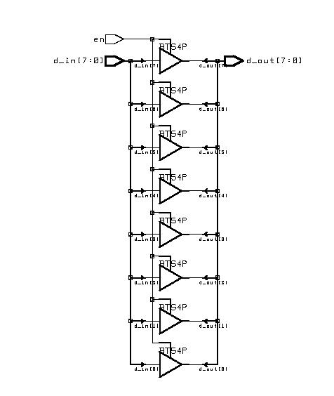
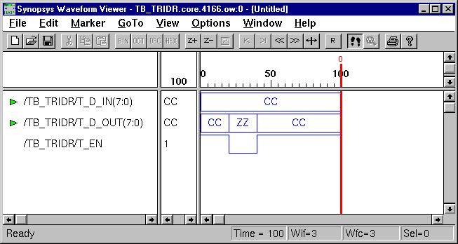
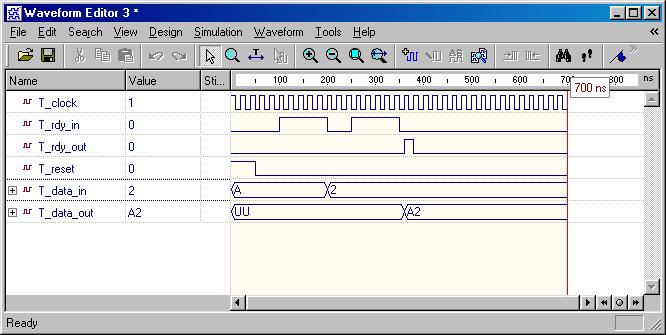
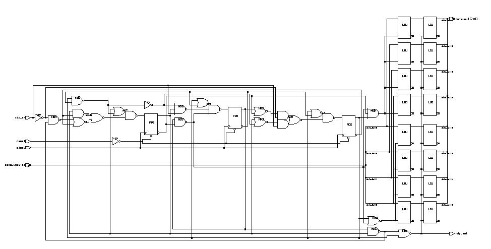
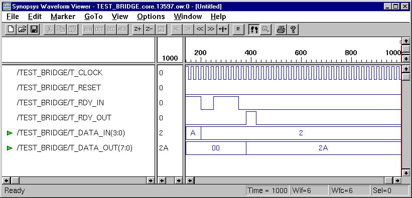
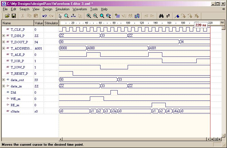
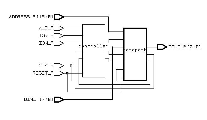
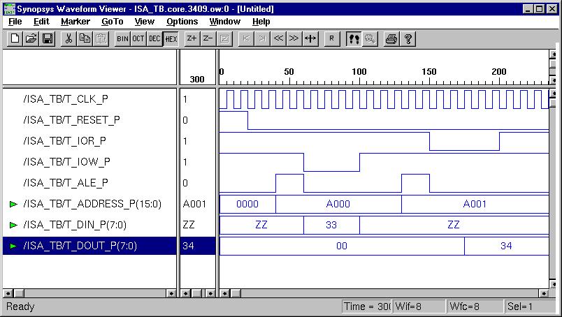
Appendix: Modeling a real industry chip - HD 6402
(ESD Chapter 4)
 
I. Specification of HD 6402 II. Behavior Modeling of UART Transmitter 
(1) Behavior Code (2) Gate-level design (3) Test Benches - 1, 2, 3 (4) Synopsys Simulation 
Case#1: one 8-bit word, 1 start, 2 stops, and even parity, or Data=11000101, Control Word=11011.  ( Gate-level Simulation )
Case#2: three 5-bit words, 1 start, 1 stop, and no parity, or Data=11010 & 00101 & 10001, Control Word=00100.  ( Gate-level Simulation )
Case#3: two 6-bit words, 1 start, 2 stops, and odd parity, or Data=110010 & 101101, Control Word=01000.  ( Gate-level Simulation )
III. Behavior Modeling of UART Receiver 
(1) Behavior Code (2) Gate-level design (3) Test Benches - 1, 2, 3 (4) Synopsys Simulation
Case#1: two 6-bit words, 1 start, 2 stops, and even parity, (Data=111001 & 100101, Control Word=01101). ( Gate-level Design Simulation )
Case#2: one 8-bit words, 1 start, 1 stop, and odd parity, (Data=10111001, Control Word=11000). ( Gate-level Design Simulation )
Case#3: three 5-bit words, 1 start, 1 stop, and no parity, (Data=01001 & 01110 & 00100, Control Word=00010. ( Gate-level Design Simulation )
IV. Structural Modeling of HD-6402 
(1) Behavior Code (2) Gate-level design (3) Test Bench (4) Synopsys Simulation

Created by Weijun Zhang (weijun_92507@yahoo.com)
at UC, Riverside, 06/2001

Saturday, January 18, 2020

Referance: Full-Monero-Node on Linux


Full-Monero-Node on Linux


Referance: 


Photo by Bruno Glätsch
With the rise of cryptocurrencies, financial privacy has become a hot topic.

Monero is currently the best in the field thanks to the fairly big anonymity set, mandatory privacy for all transactions, ring signatures, Ring CT, stealth addresses, and the future Kovri anonymization network.
Although Monero developers have mitigated most, if not all, privacy risks associated with connecting your wallet to a 3rd party node, to get a piece of mind it's recommended to run your own full node.
In this article, I'll go through steps to install and set up monero on Linux, mainly the latest Ubuntu 18.04 bionic.
However, the steps should be the same for any Debian-based distribution using systemd and fairly similar for other distros with the exception of the package manager (apt).
Sorry, no Mac or Windows.

1 Update the operating system

First, update the system packages:
sudo apt update && sudo apt-get upgrade

2 Install dependencies

Make sure you have git installed. If not, do it now:
sudo apt install git
Install the rest of dependencies:
sudo apt install build-essential cmake doxygen graphviz miniupnpc pkg-config libboost-all-dev libcurl4-openssl-dev libgtest-dev libminiupnpc-dev libreadline-dev libssl-dev libunbound-dev libunwind8-dev libzmq3-dev libzmq3-dev libpgm-dev libsodium-dev
Unfortunately, libgtest-dev doesn't come as binary on Ubuntu, so you'll have to compile it yourself:
cd /usr/src/gtest 
sudo cmake . 
sudo make -j2
sudo mv libg* /usr/lib/
How to Create a Monero Paper Wallet to Secure Your Coins

3 Download and build Monero

Create source directory if you haven't already:
mkdir ~/source
cd ~/source
Clone the repository and its submodules:
git clone --recursive https://github.com/monero-project/monerocd monero
make -j2 release # -j4 for 4 threads etc
It may take a while to compile depending on your machine.
When finished, copy all the binaries to /usr/local/bin:
sudo cp ./build/release/bin/* /usr/local/bin/
Top 5 Reasons Monero Will Become the Most Widely Used Private and Anonymous Cryptocurrency

4 Set up the service

I've written a systemd service that automatically starts the node after a reboot or when crashed.
cd /lib/systemd/system
sudo wget https://gist.githubusercontent.com/mariodian/b8bb62de8f5aa5466cccb17f280f439e/raw/db0a98573e0a8cc871781d8d43f03437ca159e22/monerod.servicesudo chmod 644 monerod.service
Make sure to edit the file to match your environment.
You may want to raise block-sync-size to a higher number if you run on a decent hardware or omit it completely and let the daemon decide automatically.
My node failed to keep up with the chain height after the April's fork so I had to set it manually.
Next, create a config file:
mkdir ~/.bitmonero
cd ~/.bitmonero
touch monerod.conf
and add the following lines:
echo "data-dir=/home/satoshi/.bitmonero" >> monerod.conf
echo "log-file=/home/satoshi/.bitmonero/monero.log" >> monerod.conf
echo "log-level=0" >> monerod.conf
If you want to be able to connect your wallet from another machine, add the following:
echo "rpc-bind-ip=0.0.0.0" >> monerod.conf
echo "rpc-bind-port=18081" >> monerod.conf
echo "rpc-login=veryLongAndRandomUsername:veryLongAndRandomPassword" >> monerod.conf
Don't forget to change rpc-login to your own one.

5 Run the service

Enable the systemd config and start the daemon:
sudo systemctl enable monerod
sudo service monerod start
You can check the progress with:
tail -f monero.log
or using a simpler output:
monerod --config-file /home/satoshi/.bitmonero/monerod.conf status
The synchronization may take from a few hours to a few days depending on your hardware.
Please be patient.

6 Allow incoming connections (optional)

You can allow two types of incoming connections to your node: P2P and RPC.
The first one lets other nodes download the chain from you. The latter lets a wallet connect to your node and retrieve info about its balance, transactions etc.
For the P2P connection run this command:
sudo iptables -I INPUT -p tcp --dport 18080 -j ACCEPT
For the RPC:
sudo iptables -I INPUT -p tcp --dport 18081 -j ACCEPT
Save the rules permanently:
sudo iptables-save
If you're behind a router, you will have to forward the ports to your machine.
Please refer to your router's manual.

7 Connect to the node with your wallet

Now test your connection from your wallet.
If you use the GUI wallet go to Settings and fill out Address and Port.
Next, under Manage Daemon click Show Advanced and type in the RPC login you've set in ~/.bitmonero/monerod.conf earlier.

In case of using the command line wallet, you may start it with the following:
monero-wallet-cli --wallet-file /path/to/your/wallet --trusted-daemon --daemon-address ip.of.your.node:18081 --daemon-login veryLongAndRandomUsername:veryLongAndRandomPassword
Personally, I prefer the command line wallet because it's cleaner and all you need, most of the time, is really just 3 or 4 commands.

The ones that you will likely use the most are:
  • show_transfers to view the list of all transactions
  • integrated_address to get a receiving address containing a payment ID
  • balance to view locked and unlocked balance
  • transfer <address> <amount> to make a payment
Type help to access the list of all commands.
*****
As you can tell, setting up Monero full node from source is fairly easy if you have basic knowledge of the Linux command line.
Optionally, to make your node more secure and anonymous, you may want to run it behind torify or torsocks (essentially the same). Unfortunately, I haven't done it myself yet so you'll have to look elsewhere.
All in all, I hope you liked the tutorial.
Please let me know in the comments section below if you run into any issues.
We hope you like the post. Please share it with your followers. Thank you for your support!
Subscribe to our newsletter for weekly thoughts and tutorials. You'll receive a FREE e-book as a bonus!

Tuesday, September 10, 2019

Difference Between HDL VHDL, Verilog, SystemVerilog; UPF

Difference Between HDL VHDL, Verilog, SystemVerilog; UPF


OptEdited Article,

What is the Difference Between HDL, VHDL, Verilog, SystemVerilog; UPF? The Designers of electronic hardware describe the behavioral structure of system  circuit designs using hardware description languages (HDLs).

This, (HDL), is a specialized programming languages commonly known as today as VHDL, Verilog, SystemVerilog, and the added UPF language is the missing link.

SystemVerilog (which includes Verilog 2001), VHDL, and UPF are parsed and processed in two steps, analysis and elaboration. Mixed VHDL and SystemVerilog compilation is fully supported via UPF.

This Elaboration supports both static elaboration and RTL elaboration.

Static elaboration elaborates the entire language that specifically binds instances to modules, resolves library references, propagates defparams, unrolls generate statements, and checks all hierarchical names/function/task calls. The result after static elaboration is an elaborated parse tree, appropriate for application simulations.

RTL elaboration is limited to the synthesize subset of the language. In addition to the static elaboration tasks for this subset, it generates sequential networks through flipflop and latch detection, and Boolean extraction. The result after RTL elaboration is a netlist, appropriate for applications such as logic synthesis and formal verification.

The netlist database stores RTL and netlist designs in a language-independent simple model based on generic gates such as The DFF, The AND, The OR, The MUX , etc.. The netlist database is common to both VHDL and SystemVerilog and has an efficient and clean API for easy integration into any existing database or object model.
  • Very memory efficient. Average overall memory usage just 300 bytes/gate.
  • Full hierarchy support, with grouping/ungrouping, etc.
  • Support for buses.
  • Compact storage of file/line/column origination info from RTL parsers.
  • Simple and clean data model and procedural Interface for easy integration with your existing database.

HDL: hardware description language (HDL) , In computer engineering, is a specialized computer language used to describe the structure and behavior of electronic circuits, and most commonly, digital logic circuits. A hardware description language enables a precise, formal description of an electronic circuit that allows for the automated analysis and simulation of an electronic circuit. It also allows for the synthesis of a HDL description into a netlist (a specification of physical electronic components and how they are connected together), which can then be placed and routed to produce the set of masks used to create an integrated circuit.  A hardware description language looks much like a programming language such as C; it is a textual description consisting of expressions, statements and control structures. One important difference between most programming languages and HDLs is that HDLs explicitly include the notion of time. HDLs form an integral part of electronic design automation (EDA) systems, especially for complex circuits, such as application-specific integrated circuits, microprocessors, and programmable logic devices.


SystemVerilog, standardized as IEEE 1800, is a hardware description and hardware verification language used to model, design, simulate, test and implement electronic systems. SystemVerilog is based on Verilog and some extensions, and since 2008 Verilog is now part of the same IEEE standard. It is commonly used in the semiconductor and electronic design industry as an evolution of Verilog.
 
Verilog, standardized as IEEE 1364, is a hardware description language (HDL) used to model electronic systems. It is most commonly used in the design and verification of digital circuits at the register-transfer level of abstraction. It is also used in the verification of analog circuits and mixed-signal circuits, as well as in the design of genetic circuits.[1] In 2009, the Verilog standard (IEEE 1364-2005) was merged into the SystemVerilog standard, creating IEEE Standard 1800-2009. Since then, Verilog is officially part of the SystemVerilog language. The current version is IEEE standard 1800-2017.[2]

VHDL (VHSIC-HDL) (Very High Speed Integrated Circuit Hardware Description Language) is a hardware description language used in electronic design automation to describe digital and mixed-signal systems such as field-programmable gate arrays and integrated circuits. VHDL can also be used as a general purpose parallel programming language.


UPF:  Verific’s UPF parser supports the entire IEEE 1801 standard (UPF 1.0, 2.0, 2.1, 3.0) and creates a UPF data model.
The UPF Parser is an integral component of Verific’s Parser Platform and interacts seamlessly with Verific’s standard SystemVerilog, VHDL, and Liberty parsers.

It natively interfaces with Verific’s data structures, and also has the ability to interface with external (non-Verific) design data.

The UPF Parser/Analyzer performs syntax and semantic checking, resolving a UPF specification into a power intent model that can be traversed and queried.

Complete file / line / column information on UPF descriptions is maintained and Verific’s comprehensive error handler is included.

The UPF Elaborator applies the power intent model to the original HDL design.

The result is a power-aware netlist with new instantiations of power-related cells, as well as any required supply network and corresponding control path logic.

UPF concepts elaborated in an HDL design include logic and supply ports and nets, power switches, and retention, isolation, level-shifter and repeater cells.

Verific’s UPF parser is also easily integrated with external (non-Verific) data structures.

Analysis creates parse-trees and performs type-inferencing to resolve the meaning of identifiers.

The Parser/Analyzer modules support the entire SystemVerilog IEEE 1800 (including Verilog IEEE 1364), VHDL IEEE 1076, and UPF IEEE 1801 languages, all revisions, without any restrictions. The resulting parse trees / data models come with extensive APIs.

They differ from software programming languages because they include a means of describing propagation time and signal strengths.

These days, (2019-*), it would be impossible to design a complex system on a chip (SoC) for a mobile device or any other consumer electronics product without an HDL.

Each of the three HDLs has its own distinct style.

VHDL and Verilog implement register-transfer-level (RTL) abstractions.

When they were first introduced in the late 1980s, they were considered breakthrough technologies because they enabled engineers to work at a higher level of abstraction with RTL simulators.

Previously, engineers simulated their designs at the schematic or gate level.

SystemVerilog was developed to provide an evolutionary path from VHDL and Verilog to support the complexities of SoC designs.

It’s a bit of a hybrid—the language combines HDLs and a hardware verification language using extensions to Verilog, plus it takes an object-oriented programming approach.

SystemVerilog includes capabilities for test-bench development and assertion-based formal verification.

The U.S. Department of Defense funded VHDL, and Gateway Design Automation developed Verilog to drive the Verilog simulator.

Cadence Design Systems, once it acquired Gateway, placed the Verilog HDL into the public domain and it became an industry standard.

In the early 1990s, the electronics industry was forced to contend with the “language wars,” where competing factions in either the VHDL or Verilog camp competed for an engineer’s desktop mindset.

Both languages survived and now coexist, often in the same design flow -i.e. Xilinx.com.

Co-Design designed SystemVerilog, initially known as SUPERLOG.

After Synopsys acquired Co-Design, SUPERLOG/SystemVerilog was placed in the public domain as well.

All three are IEEE industry standards –– VHDL is IEEE 1076-2008, Verilog is IEEE 1364-2005 and SystemVerilog is IEEE 1800-2012.

The IEEE works cooperatively with the industry standards organization Accellera, which acts as its steward and develops many of IEEE’s technology standards for system-level design, modeling, and verification.

My company, (Rob Dekker, CTO & Founder, Verific Design Automation ), Verific Design Automation, has built parsers and elaborators for VHDL, Verilog, and SystemVerilog since 1999.

Comparing VHDL, Verilog, SystemVerilogVHDL and Verilog are considered general-purpose digital design languages, while SystemVerilog represents an enhanced version of Verilog.

Each has its own style and characteristics.

VHDL has roots in the Ada programming language in both concept and syntax, while Verilog’s roots can be tracked back to an early HDL called Hilo and the C programming language.

VHDL is a rich and strongly typed language, deterministic and more verbose than Verilog.

With Verilog and VHDL, engineers can represent the desired functionality as a software program.

Then the model is simulated to confirm the design will work as intended.

Any problems can be corrected in the model, and simulation will verify the correction.
 
As a result, designs written in VHDL are considered self-documenting.

Its syntax is non-C-like and engineers working in VHDL need to do extra coding to convert from one data type to another.

VHDL often catches errors missed by Verilog.

VHDL emphasizes unambiguous semantics and allows portability between tools.

Sample VHDL Code:
reg1: process (rst, clk)
    begin
    if  rst = '1' then
        q_reg <= (others => '0');
        q_i <= (others => '0');
    elsif  rising_edge(clk) then
        if  s_l = '1' then
        q_i(0) <= q_i(7);
        loop1:  for i in 6 downto 0 loop
            q_i(i + 1) <= q_i(i);
        end loop loop1;
        q_reg <= y;
        else
        q_i <= q_reg;
        q_reg <= y;
        end if;
    end if;
    end process reg1;


Verilog is weakly typed and more concise with efficient notation.

It is deterministic.

All data types are predefined in Verilog and each has a bit-level representation.

Syntax is C-like.

Sample Verilog Code:
always @(posedge CLK or posedge RST)
begin
  if (RST) begin
     q_reg = 0;  
 Q = 0;   
 end else if (S_L) begin
     Q[7:0] = {Q[6:0],Q[7]}; 
 q_reg = Y;
 end else begin
     Q = q_reg;  
 q_reg = Y;  
 end
end


SystemVerilog includes a set of extensions to the Verilog HDL to help engineers design and verify larger and more complex designs.

In fact, many industry watchers consider it the first Hardware Description and Verification Language (HDVL), because it combines VHDL and Verilog features with those of Hardware Verification Languages (HVLs) Vera and e, as well as C and C++.

It’s targeted at RTL coding, using constrained random techniques for assertion-based and coverage-driven verification.

Sample SystemVerilog Code:
property p_push_error; 
    @ (posedge clk) 
   not (b_if.push && b_if.full && !b_if.pop); 
  endproperty : p_push_error
  ap_push_error_1 : assert property (p_push_error);
  property p_pop_error; 
   @ (posedge clk) 
   not (b_if.pop && b_if.empty); 
  endproperty : p_pop_error
  ap_pop_error_1 : assert property (p_pop_error);

always_ff @ (posedge clk) begin
    b_if.error <= (b_if.pop && b_if.empty) || (b_if.push && b_if.full && !b_if.pop);


Because of its structure, VDHL catches most errors early in the design process.

Verilog, on the other hand, enables engineers to quickly write models.

SystemVerilog attempts to capture the best features of both, and includes features of HVLs to support test-bench development and formal verification techniques.